Refine Your Search

Topic

Author

Affiliation

Search Results

Technical Paper

2-D Soot Visualization in Unsteady Spray Flame by means of Laser Sheet Scattering Technique

1991-02-01
910223
The two-dimensional distribution of a soot cloud in an unsteady spray flame in a rapid compression machine(RCM) was visualized using the laser sheet scattering technique. A 40 mm x 50 mm cross section on the flame axis was illuminated by a thin laser sheet from a single pulsed Nd:YAG laser(wavelength 532 nm). Scattered light from soot particles was taken by a CCD camera via a high speed gated image intensifier. The temporal variation of the scattered light images were presented with the injection pressure as a parameter. The results showed that scattered light was intense near the periphery of the flame tip and that the scattered light becomes weaker significantly and disappears fast after the end of injection as injection pressure is increased. This technique was also applied to the visualization of the two-dimensional distribution of liquid droplets in the non-evaporating spray to correlate it with the soot concentration distribution.
Technical Paper

2-D Visualization of liquid and Vapor Fuel in an I.C. Engine

1988-02-01
880521
A sheet of laser light from a frequency tripled Nd-YAG laser approximately 200μm thick is shone through the combustion chamber of a single cylinder, direct injection internal combustion engine. The injected decane contains exciplex—forming dopants which produce spectrally separated fluorescence from the liquid and vapor phases. The fluorescence signal is collected through a quartz window in the cylinder head and is imaged onto a diode array camera. The camera is interfaced to a microcomputer for data acquisition and processing. The laser and camera are synchronized with the crankshaft of the engine so that 2—D images of the liquid and vapor phase fuel distributions can be obtained at different times during the engine cycle. Results are presented at 600, 1200 and 1800 rpm, and from the beginning to just after the end of injection. The liquid fuel traverses the cylinder in a straight line in the form of a narrow cone, but does not reach the far wall in the plane of the laser sheet.
Technical Paper

2-Stage Torque Converter and Double Clutch

1952-01-01
520220
THE development of the two-stage torque converter with automatic double clutch is presented here. The author covers particularly the substitution of casting for fabrication for several of the units in the transmission.
Technical Paper

2.5 D LED: A Cost Efficient Solution for 3 D Signaling Lamps

2007-04-16
2007-01-1231
After the first appearance of LED rear lamps, which employed mainly two-dimensional arrays of LEDs, the request of stylists and OEMs to have three-dimensional LED alignment has increased strongly. Development of more powerful LEDs and new packaging and assembly technologies now allows for a three-dimensional assembly of the LEDs, giving an impression of depth and enabling the LEDs to follow even extreme curvatures. This gives great customer satisfaction in terms of styling, but the disadvantage is that the cost for the three-dimensional LED alignment increases significantly. To counteract this development, we have developed a light guide technology approach (so-called 2.5 D) to combine a cost efficient LED assembly process with the flexibility of a 3 D arrangement of the light sources. Thus, we can use standard planar FR4 (Flame Resistant 4) LED printed circuit boards with arbitrary LEDs and do not depend on a certain assembly technology.
Technical Paper

20 A Combined Experimental and Numerical Approach for Motorcycle Crank Noise: Experimental Validation

2002-10-29
2002-32-1789
The demands for comfort and a cleaner environment have been increasing for the past years for motorcycle as well as car manufacturers. With the need to decrease the time-to-market, there is a clear drive to apply CAE-based methods in order to evaluate new designs and to propose design changes that solve any identified problems. More specifically, the demands on the comfort of the rider are not only related to ride & handling and vibration levels(1), but also to the noise levels generated by the motorcycle. This paper presents the virtual modeling of one-cylinder engine of a motorcycle that identifies the mechanism behind the generation of an annoying noise. Furthermore, different possible design changes were evaluated in order to solve the problem. A combined experimental and numerical approach was followed to achieve this. Experiments were used to identify important parameters that determine the engine behavior and thus are critical for the modeling of such an engine.
Technical Paper

2005 Ford GT - Interior Trim & Electrical

2004-03-08
2004-01-1256
Driven by a tight vehicle development schedule and unique performance and styling goals for the new Ford GT, a Ford-Lear team delivered a complete interior and electrical package in just 12 months. The team used new materials, processes and suppliers, and produced what may be the industry's first structural instrument panel.
Technical Paper

2005 Ford GT - Melding the Past and the Future

2004-03-08
2004-01-1251
The 2005 Ford GT high performance sports car was designed and built in keeping with the heritage of the 1960's LeMans winning GT40 while maintaining the image of the 2002 GT40 concept vehicle. This paper reviews the technical challenges in designing and building a super car in 12 months while meeting customer expectations in performance, styling, quality and regulatory requirements. A team of dedicated and performance inspired engineers and technical specialists from Ford Motor Company Special Vehicle Teams, Research and Advanced Engineering, Mayflower Vehicle Systems, Roush Industries, Lear, and Saleen Special Vehicles was assembled and tasked with designing the production 2005 vehicle in record time.
Technical Paper

2005 Ford GT Electrical & Electronics

2004-03-08
2004-01-1259
The Ford GT Program Team was allocated just 22 months from concept to production to complete the Electrical and Electronics systems of the Ford GT. This reduced vehicle program timing - unlike any other in Ford's history -- demanded that the team streamline the standard development process, which is typically 54 months. This aggressive schedule allowed only 12 weeks to design the entire electrical and electronic system architecture, route the wire harnesses, package the components, and manufacture and/or procure all components necessary for the first three-vehicle prototype build.
Technical Paper

2005 Ford GT Magnesium Instrument Panel Cross Car Beam

2005-04-11
2005-01-0341
Ford GT 2005 vehicle was designed for performance, timing, cost, and styling to preserve Ford GT40 vintage look. In this vehicle program, many advanced manufacturing processes and light materials were deployed including aluminum and magnesium. This paper briefly explains one unique design concept for a Ford GT instrument panel comprised of a structural magnesium cross-car beam and other components, i.e. radio box and console top, which is believed to be the industry's first structural I/P from vehicle crash load and path perspectives. The magnesium I/P design criteria include magnesium casting properties, cost, corrosion protection, crashworthiness assessments, noise vibration harshness performance, and durability. Magnesium die casting requirements include high pressure die cast process with low casting porosity and sound quality, casting dimensional stability, corrosion protection and coating strategy, joining and assembly constraints.
Technical Paper

2006 Chevrolet Corvette Z06 Aluminum Spaceframe

2005-04-11
2005-01-0465
This paper describes the engineering, manufacturing and integration necessary to produce the Corvette's first ever all-aluminum spaceframe (see Figure 1). The engineering and manufacturing of the spaceframe was a joint venture between General Motors and suppliers ALCOA (Aluminum Company of America) and Dana Corporation. ALCOA led the initial design of the spaceframe; Dana Corp led the manufacturing; General Motors' Engineering and Manufacturing groups led the integration of the assembly. The aluminum spaceframe design is modeled after the baseline steel structure of the Corvette coupe. The aluminum spaceframe reduces 140 lbs from the steel baseline and enters the plant at 285 lbs. This frame allows the 2006 Corvette Z06 to enter the market at a 3100 lbs curb weight. Aluminum casting, extruding, stamping, hydroforming, laser welding, Metal Inert Gas (MIG) welding, Self Pierce Riveting (SPR), and full spaceframe machining make up the main technologies used to produce this spaceframe.
Technical Paper

2006 Chevrolet Corvette Z06 Aluminum Spaceframe Design and Engineering Technology

2005-04-11
2005-01-0466
The General Motors (GM) Corvette design team was challenged with providing a C6 Z06 vehicle spaceframe that maintained the structural performance of its C5 predecessor while reducing mass by at least 56 kg. An additional requirement inherent to the project was that the design must be integrated into the C6 assembly processes with minimal disruption, i.e. seamless integration. In response to this challenge, a collaborative team was formed, consisting of design engineers from General Motors, Alcoa and Dana Corporation. The result of this collaborative effort is an aluminum Z06 spaceframe that satisfies the high performance expectations of the vehicle while reducing the mass by approximately 62 kg. The frame consists of aluminum extrusions, castings and sheets joined by MIG welding, laser welding and self-piercing rivets. The extrusions are 6XXX series alloys, the castings are permanent mold A356 while the sheet panels are formed from the 5XXX series of alloys.
Technical Paper

2006 Chevrolet Corvette Z06 Aluminum Spaceframe Manufacturing Technology

2005-01-11
2005-01-0470
In October 1999, General Motors contracted Dana Corporation to manufacture an all-aluminum spaceframe for the 2006 Chevrolet Corvette Z06. Corvette introduced its first ever all-aluminum frame (see Figure 1) to the world at the 2005 North American International Auto Show (NAIAS) in Detroit, Michigan. The creation of this spaceframe resulted in a significant mass reduction and was a key enabler for the program to achieve the vehicle level performance results required for a Z06 in an ever-growing market. Dana Corporation leveraged ALCOA's (Aluminum Company of America) proven design capabilities while incorporating new MIG welding, laser welding, Self-Pierce Riveting (SPR), and full spaceframe machining to join General Motors (GM) Metal Fabrication Division's (MFD) hydroformed rails to produce the Corvette Z06's yearly requirement of 7000 units. This paper describes the technologies utilized throughout the assembly line and their effect on the end product.
Technical Paper

2006 Corvette Z06 Carbon Fiber Fender- Engineering, Design, and Material Selection Considerations

2005-04-11
2005-01-0468
General Motor's Corvette product engineering was given the challenge to find mass reduction opportunities on the painted body panels of the C6 Z06 through the utilization of carbon fiber reinforced composites (CFRC). The successful implementation of a carbon fiber hood on the 2004 C5 Commemorative Edition Z06 Corvette was the springboard for Corvette Team's appetite for a more extensive application of CFRC on the C6 Z06 model. Fenders were identified as the best application for the technology given their location on the front of the vehicle and the amount of mass saved. The C6 Z06 CFRC fenders provide 6kg reduction of vehicle mass as compared to the smaller RRIM fenders used on the Coupe and Convertible models.
Technical Paper

2006 Corvette Z06 Carbon Fiber Structural Composite Panels- Design, Manufacturing and Material Development Considerations

2005-04-11
2005-01-0469
The General Motors Corvette Product Engineering Team is in a continual search for mass-reduction technologies which provide performance improvements that are affordable and add value for their customers. The structural composite panels of the C6 Z06 provided a unique opportunity to extend the use of carbon fiber reinforced materials to reduce mass and enhance performance. The entire vehicle set of composite panels was reviewed as candidates for material substitution, with the selection criteria based on the cost per kg of mass saved, tooling cost required, and the location of the mass to be saved. Priority was extended to mass savings at the front of the vehicle. After a carefully balanced selection process, two components, both requiring redesign because of the Z06’s wider stance, met the criteria: the Front Wheelhouse Outer Panel and Floor Panels. The current Floor Panels, first used on the C5, are large and are a balsawood-cored glass fiber reinforced composite design.
Book

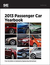
2013 Passenger Car Yearbook

2013-10-07
Each year car manufacturers release new production models that are unique and innovative. The production model is the result of a lengthy process of testing aerodynamics, safety, engine components, and vehicle styling. The new technologies introduced in these vehicles reflect changing standards as well as trends of the market. From Acura to Volvo, this book provides a snapshot of the key engineering concepts and trends of the passenger vehicle industry over the course of a year. For each of the 43 new production models, articles from Automotive Engineering International (AEI) magazine detail technology developments as well as a comprehensive look at the 2013 passenger car models. This book provides those with an interest in new vehicles with all the information on the key automotive engineering and technology advancements of the year.
Book

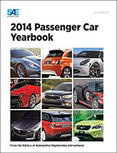
2014 Passenger Car Yearbook

2013-12-10
Each year car manufacturers release new production models that are unique and innovative. These cars begin as concepts then go through the process of prototyping. The process of creating a new model can take years, involving extensive testing and refining of aerodynamics, safety, engine components, and vehicle styling. The production model is the result of this lengthy process, and its new technologies reflect the latest engineering standards as well as market trends. The 2014 Passenger Car Yearbook details the key engineering developments in the passenger vehicle industry of the year. Each new car model is profiled in its own chapter with one or more articles that were previously published and written by the award-winning editors of Automotive Engineering International. The novel engineering aspects of each new model are explored in depth.
Book

2016 Mobility Engineering Professionals Salary Survey

2016-07-14
EXCLUSIVE MEMBER BENEFIT: 2016 MOBILITY ENGINEERING PROFESSIONAL SALARY SURVEY AND CALCULATOR Gain better insight into compensation practices: this salary survey is the only study its kind to explore levels and changes in compensation and employment for engineers and technical employees in the automotive, aerospace, and commercial vehicle industries. It benchmarks compensation levels based by geography, education, industry sector, experience, and managerial and budgetary responsibility. The full report is available to SAE International members by signing into your My SAE account and downloading it into your My Library area. Members also have full access to the updated online interactive salary calculator by visiting SAE’s website. Become a member of SAE International to access this exclusive benefit for free, or purchase it today. YOU BELONG HERE. Membership helps you succeed both personally and professionally. Join us today.
Technical Paper

22M-0156, Loading Classification for Fatigue Design Applied to Automotive Time-Series

2022-03-29
2022-01-0254
This study focuses on variable amplitude loadings applied to automotive chassis parts experiencing carmaker’s specific proving grounds. They are measured with respect to time at the wheel centres and composed of the six forces and torques at each wheel, within the standard vehicle reference frame. In the scope of high cycle fatigue, the loadings considered are supposedly acting under the structure yield stress. Among the loadings encountered during the vehicle lifetime, two classes stand out: Driven Road: loads measured during the vehicle manoeuvre; Random Road: loads mainly coming from the road asperity. To separate both effects, a frequency decomposition method is proposed before applying any lifetime assessment methods. The usual Rainflow counting method is applied to the Driven Road signal. These loadings, depending on the vehicle dynamics, are time-correlated. Thus, the load spectra is set only thanks to the vehicle accelerations time-measurement.
Technical Paper

250 °C SiC Power Module Package Design

2008-11-11
2008-01-2892
In order to take full advantage of SiC, a high temperature package for power module using SiC devices was designed, developed, fabricated and tested. The details of the material selection and fabrication process are described. High temperature reliability test and power test shows that the package presented in this paper can perform well at the high junction temperature.
Technical Paper

270-Vdc/Hybrid 115-Vac Electric Power Generating System Technology Demonstrator

1991-09-01
912051
Sundstrand is investigating 270-Vdc/hybrid 115-Vac electrical power generating and distribution systems technology so as to be well prepared to offer such systems for future aircraft applications. The approach taken has been to design, build, and test a representative system that meets or exceeds the tightest of the performance standards as defined by miliary standards. This paper describes a single-channel, 120-kW hybrid system and presents some typical performance data. The dc bus supplies a 30-kVA, 400-Hz, 115-Vac inverter; constant power load banks of up to 150 kW; and a resistive load bank of up to 90 kW. System simulation studies indicated the potential for unstable operation due to the negative impedance of the constant power load in conjunction with the source ripple filter and the load EMI filters. Unstable voltage and current were observed in system testing when the magnitude of the source impedance was not sufficiently below that of the load impedance.
X